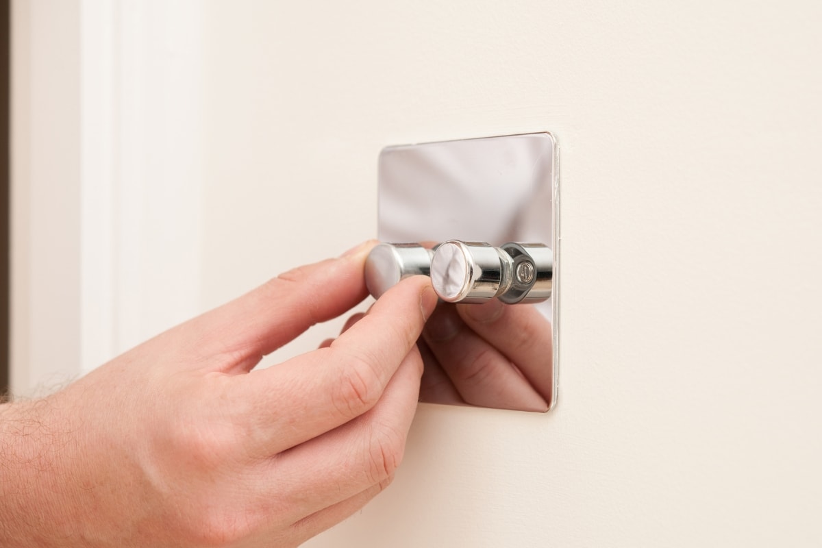
Dimmers are one of the most popular lighting controls installed in our homes as well as in commercial lighting. Dimmer switches can control the intensity of the light output to help us create the perfect mood with a fantastic atmosphere for every occasion and help save money on your electric bills. If you want to replace and upgrade your regular light switch with a dimmer, you might wonder which type to choose from because there are various types of dimmers on the market.
In this article, we will walk you through what a dimmer is and how they work to help you select the best dimmer switch for your lights.
What Is a Dimmer Switch
A dimmer switch is an electronic device designed to adjust the brightness of the light output emitted by LED, CFL, fluorescent, halogen, or incandescent lamps. The brightness of a light source is measured in lumens, meaning the total output of the visible light. When the light is dimmed, it produces less light output, so the brightness decreases.
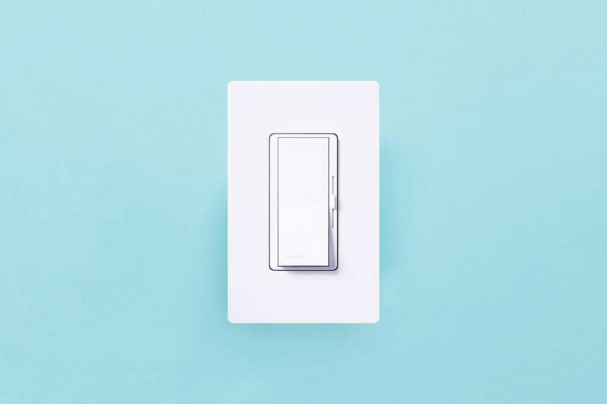
Most dimmers are dimmer switches that can directly replace a light switch. Other types of dimmers include in-line, plug-in, rotary, push types, etc. The form of a dimmer depends on its actual use cases.
How Does a Dimmer Work
Basically, all types of dimmers adjust the brightness of the light output by reducing the power delivered to the light source. The less power is delivered, the dimmer the light is. Depending on how dimmers alter the voltage, there are two major types of dimmers: mains dimmers and low voltage dimmers.
Simply put, the difference is:
- Mains dimmers directly adjust the input mains AC voltage to the light to control the brightness.
- Low voltage dimmers do not adjust the mains AC input voltage. They only send control signals to the external ballasts or drivers connected to the low-voltage lighting. The dimmable ballasts or drivers adjust the voltage delivered to the light to control the brightness.
Mains Dimmer
Mains dimmer switches directly adjust the 110-120V AC mains voltage delivered to the lights, thus the name mains dimmer. The more power is delivered to the light, the brighter the light is. The less power is delivered, the dimmer the light is. Mains dimmers are also known as phase dimmers or phase-cut dimmers because they use the phase-cut dimming method to alter the mains voltage.
Main dimmer switches are mostly used in residential lighting as most residential lights, especially LED bulbs, have interior drivers built inside the fixture. Interior drivers make residential lighting look better at a lower cost and are very convenient for users to use by simply plugging the light into the socket. Main dimmer switches work directly on the input mains voltage to the light source so that users don’t have to deal with the drivers. Most dimmer switches you use and see every day are mains dimmers, also called line voltage dimmers.
How does the dimmer switch adjust the voltage?
Early and old dimmer switches simply use a variable resistor to produce a decreased voltage by increasing the resistor. The problem with the old design is that the resistor still consumes a massive amount of electricity and releases it in the form of heat, which is very inefficient and unsafe.
Modern dimmer switches are more efficient that they use phase-cut dimming to reduce the voltage. They use a semiconductor to quickly chop off(trimming) part of the AC voltage waveform(phase) 120 times per second(twice per cycle) so that only part of the AC sine wave is passed to the light. The more phase-cut per sine wave, the less voltage is delivered to the light and the dimmer the light is. In other words, the dimmer switch rapidly turns the light on and off 120 times per second with a delay in between. The longer you turn the light off, the dimmer the light is.
As the on and off are switched so rapidly, human eyes cannot notice any difference or flickering, and it does not affect the light’s quality or the bulb’s lifespan. Depending on how the voltage waveform is cut at the zero-crossing point, there are mainly two types of phase-cut dimmers: the leading edge dimmers and the trailing edge dimmers.
Leading Edge Dimmer
Leading edge dimmer cuts off the front edge of each sine wave’s half circle, meaning they switch off the current at the zero-crossing point and switch on again after a delay. Leading edge dimmers use a semiconductor device called TRIAC(Triode for Alternating Current) for phase cutting. A TRIAC acts as a high-speed switch that turns the lights on and off 120 times a second, trimming both half cycles. Due to TRIAC’s ability to switch high levels of voltage and current, TRIAC leading edge dimmers are also ideal for handling high AC voltage, controlling fans and motors speed, and other AC control applications. A leading edge dimmer is also referred to as a forward phase dimmer, MLV dimmer, or TRIAC dimmer. Leading edge dimmers are the most common and traditional dimming method.
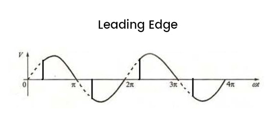
As leading edge dimming cuts the front edge of every half circle, it will result in a rush of current to the light source. The rush of voltage does not affect or cause resistive loads like incandescent bulbs to flicker and the hot filament does not heat up or cool down instantly when the voltage changes which also helps eliminate flickering. Incandescent lights work well with all types of dimmers.
However, the inrush voltage might cause LED and CFL bulbs to flicker or buzz because electronic lights are very sensitive to voltage. Additionally, due to how TRIAC works, leading edge dimmers have a high minimum load, which makes them not suitable for handling low-energy lighting like LEDs and CFLs.
Theoretically, leading edge dimmers work well with incandescent bulbs but are generally not suitable for dimming LED lights. As technology improves, manufacturers have developed modern leading edge dimmers that work well with CFL and LED loads. Bulb manufacturers also introduced retrofit LEDs bulbs that are made to replace incandescent bulbs and are compatible with most dimmers, including the standard leading edge dimmer. Most leading edge dimmers don’t require neutral wire, meaning less rewiring is required for installation. This also makes leading edge dimmers the ideal type for home retrofits.
Leading edge dimmers are typically used to control resistive loads such as traditional incandescent or halogen light sources and inductive loads such as magnetic low voltage(MLV) transformers. Leading edge dimmers work well with MLV light sources and are able to handle up to 10000watts of load and can protect MLV transfers from overheating or damage from voltage spikes.
MLV dimmers are a kind of leading edge dimmers designed to control MLV lighting which uses a magnetic low voltage(MLV) transformer in their lighting systems. The transformer is to reduce the voltage and increase the current to make lights more effective. MLV transformers are a bit heavy and large, containing a couple of coils. You can find MLV transformers used in recessed lights, under cabinet lights, older chandeliers or some led strip lights with a large MLV transformer.
Trailing Edge Dimmer
Trailing edge dimmer cuts off the end edge of each sine wave’s half circle, meaning they switch the current on at the zero crossing point and switch off later in the mains cycle. Trailing edge dimmers use more sophisticated electronic systems like MOSFET’s and IGBT’s semiconductors for phase cutting. A trailing edge dimmer is also referred to as a reverse phase dimmer, ELV dimmer, or electronic dimmer.
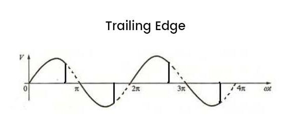
As the electrical current is cut off at the end of the AC input waveform, trialing edge dimmer will not cause a rush of voltage and can provide smooth dimming with nearly no buzzing sound. Compared to leading edge dimmers, trailing edge dimmers have a lower minimum load that can handle low-energy bulbs like LEDs very well. However, they also have low load capacity limited to about 150w output. Most trailing edge dimmers require a neutral wire for installation that allows the dimmer to draw power from and provide smooth and silent dimming operation. This also makes trailing edge dimmers perform well in low wattage ranges and can dim the lights down to 5% light levels.
Trailing edge dimmers are ideal for dimming LED lights and can dim incandescent light bulbs more effectively than leading edge dimmers. Though some LEDs are made to be compatible with both leading edge and trailing edge dimmers, such as retrofit LEDs that are made to be installed on existing incandescent dimmers. It’s better to choose a trailing edge dimmer for better performance.
Trailing edge dimmers are typically used to control capacitive loads such as electronic low voltage(ELV) transformers, electronic drivers and LEDs, as well as dimmable CFLs with integrated ballast, incandescent and halogen lamps. Trailing edge dimmer switches are also more complex and expensive than leading edge dimmers.
ELV dimmers are a kind of trailing edge dimmers designed to control ELV lighting that uses an electronic low voltage(ELV) transformer in their lighting systems. They are also the standard for dimming LED lighting as LED is also electronic low voltage. ELV transformers are smaller and slimmer than MLV transformers so they are much more convenient to use and can be mounted on track lights. You can find ELV transformers used in low voltage fixtures like LEDs, ELV track lighting, under cabinet lighting, and LED strips.
Universal Dimmer
Universal dimmers are designed to work with all incandescent, halogen, dimmable LED, and dimmable CFL bulbs. Universal dimmers have a microcontroller that allows users to switch the dimmer between the leading edge and trailing edge types to select the best dimming system for the connected lights. Some universal dimmers are also designed for controlling MLV and ELV loads as well.
Low Voltage Dimmer
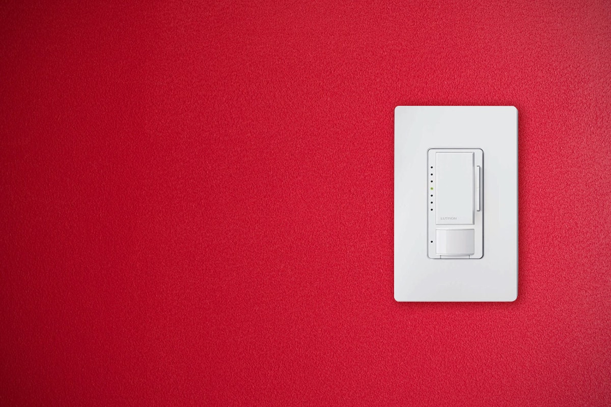
Low voltage dimmers are used to dim low-voltage lighting with external ballasts or drivers. Low voltage lighting is mostly used in commercial applications because the external drivers can handle heat emission well, are easy for maintenance and replacement jobs, and are possible to manage and arrange many lighting individually in groups by controlling via the driver.
There are three major devices in a low voltage dimming system: the low voltage dimmer, the external driver, and the low voltage lights. The main difference between a low voltage and mains dimmer is that the low voltage dimmer does not directly alter the voltage delivered to the lights. Instead, they only send control signals to the driver via additional control cables. The driver in a low voltage dimming system is called a dimming driver because it does the job of both a driver and a dimmer. The driver will regulate the input AC power from the mains to low voltage DC voltage as a driver and adjust the voltage output to the lights as a dimmer after receiving control signals from the low voltage dimmer.
There are several standards for how the dimmer sends signals and communicate with the driver. The standards are called communication protocols. Similarly, there are several ways for how the driver adjusts the brightness of the light output, and they are referred to as dimming methods. This is why there are so many variations when it comes to low voltage dimmers.
Dimming Communication Protocols
There are different lighting communication protocols for LED drivers. The most commonly used systems in professional LED lighting are 0-10V, 1-10V, DALI, and DMX. For each protocol, you need to use a corresponding dimmer switch. For example, you need to use a 0-10v dimmer switch to control a 0-10V dimming driver.
Every dimming protocol has its own characteristics, pros, and cons. Which protocols and dimmer switches to choose depends on your requirements for the lighting application.
0-10V
0-10V dimming protocol is one of the first and simplest lighting controls introduced for fluorescent dimming ballasts first and then improved to adapt to LED dimming drivers. It’s recognized by IEC standard 60929 Annex E and is still widely used and accepted today.
0-10V dimming is analog dimming. The 0-10V dimmer sends an analog 0V to 10V low voltage DC control signal to the dimming driver. The driver receives the control signal via the two additional control cables and then alters the voltage output delivered to the LED to adjust the brightness.
It can provide very smooth dimming controls even at 0.1% light level compared to phase dimming. When the control signal is at 10V or above, the light will output at 100% full brightness. At 0V, the driver outputs the minimal voltage to the LED allowed by the driver. Some dimming drivers can output as low as 10% of max voltage so that the LED can be dimmed down to 10% light level by the dimmer. In this case, you will need to add an extra light switch to be able to turn off the light completely. Advanced dimming drivers can output 0.1% to 0% of the max voltage, meaning you can turn off the light with the 0-10V dimmer switch only. As 0-10V dimmers only send out control signals rather than directly adjusting the mains AC voltage, it is also safer and more effective to use and can easily handle thousands of watts of loads on a single dimmer.
1-10V
1-10V dimming is very similar to 0-10V dimming. They are both analog dimming that use low voltage analog signals to communicate with the driver and do not directly adjust the mains voltage delivered to the driver. They both do not support bidirectional communication, meaning you cannot get status feedback from the light.
0-10V and 1-10V dimming both can dim the light to 0%, as long as the LED and the driver have the capability to dim down to 0%. It does not mean that a 1-10V dimmer can only dim down to 10% and a 0-10V can dim down to 0%. These dimmer switches just send control signals. The 0(1)V and 10V are just the low point and high point of the signal. It’s the dimmable drivers who adjust the output voltage to dim the LED given the signal from the 0(1)-10V dimmer. They both can provide a linear dimming pattern on light output between 0(1) and 10V, where 10V at full brightness and 0(1)V at minimal brightness.
Let’s discuss the difference between 0-10V and 1-10V.
0–10 V lighting controls have two control types, or standards that are recognized: current sourcing and current sinking. Usually, 0-10V is referred to as current sourcing which is a theatrical dimming standard, and 1-10V is referred to as current sinking which is a dimming ballast standard at the beginning but is also used for LED dimming drivers recently.
The 0-10V dimmer is a current source standard recognized by ESTA E1.3, Entertainment Technology – Lighting Control System – 0-10V Analog Control Protocol, which means that the current flows from the dimmer to the driver. In other words, the dimmer provides power(source) and outputs the 0-10V DC control signal to the driver. That’s why most 0-10V dimmers are 4-wire devices because they need to connect to both the mains voltage and driver. At 0V, the light should be at its minimal light level, ideally at 0% light level or off. 0-10V dimmers are usually used for entertainment lighting such as theatrical lighting.
The 1-10V dimmer is a current sink standard recognized by IEC 60929 Annex E, which means that the current flows from the driver to the dimmer. In other words, the dimmer receives 10V DC power from the driver(sink) and returns a reduced voltage back to the driver. Most 1-10V dimmers are simple 2-wire devices because they only connect with the driver. At 1V, the ballast/driver outputs its minimum light level and any voltage less than 1 volt is defined as minimum. If the minimum output is 0%, the dimmer can turn off the light completely by itself. If the minimum output is not 0%, you need to add a separate switch to be able to turn off the light. 1-10V dimmers are usually used for general lighting.
DALI
DALI stands for Digital Addressable Lighting Interface. It’s the first digital lighting control protocol with bidirectional communication recognized by IEC62386. DALI is a very flexible system that allows you to create different groups for lighting control and control each individual light separately with easy wiring. DALI is a bidirectional protocol which means it can receive the feedback status of the controlled lighting via the same control cable, such as the current brightness level and can be used along with light sensors and occupancy sensors.
DALI dimming has two polarity independent DA control cables required to connect the DALI bus, which provide fewer installation errors and less expensive wiring setup. DALI can also give the most accurate and widest dimming range, being able to reduce the intensity of light up to 0.1% and can control RGBW as well.
DALI is mainly used in general lighting applications like office lighting, museum lighting and hospital lighting. DALI 1 only supports a maximum of 64 independent addresses while DALI 2 can support up to 128 devices. However, DALI requires specialized knowledge for installation and hardware & software commissioning and is less suitable for fast brightness changes.
DMX
DMX, also known as DMX512, stands for Digital Multiplex with 512 pieces of information which means one DMX can control 512 individual addresses. It’s a standard for digital communication networks that are commonly used to control lighting and effects, originally intended as a standardized method for controlling stage lighting in theatres and now mostly used as stadium lights, underwater swimming pool lighting, home theater lighting or color dynamic architectural lighting.
DMX is a unidirectional protocol, meaning it can only send signals to the driver. With RDM(Remote Device Management) being introduced that adds bidirectional communication to DMX, DMX/RDM can automatically address each channel and get the feedback status report from connected lighting.
DMX requires three control signal cables and is more expensive than the other lighting controls. It’s very fast in changing the intensity and color of lighting, which is very suitable for dynamic light shows. It can support a long distance of up to 300 meters between the controller and the last driver. DMX also requires specialized knowledge for installation and commissioning.
Push Dimming
Push dimming is a simple analog dimming method with only 3 wires connected to the driver: a live wire, a neutral wire, and a switching contact from the retractive switch. Normally a short push of the switch turns the driver on and off. A long push of the switch adjusts the intensity of light from bright to dim. Push dimming is also called push dim or switch dim.
Dimming Methods
After the dimmer sends control signals to the dimming driver, the driver needs to adjust and reduce the output voltage to dim the lights. There are two dimming methods: analog dimming and PWM dimming.
Analog Dimming
Analog dimming, also known as constant current reduction(CCR), adjusts the light output by directly controlling the DC current flowing to the LED. Analog dimming follows the mechanism that the amount of light output is approximately proportional to the current flowing through the LED. You can dim LEDs as low as possible, as long as the driver allows to output such low current.
With analog dimming, the LEDs are driven below the rated current as you dim down the light. Without being able to function under the rated current, as a result, the LEDs may fail to deliver precise light output with color shifts and incorrect color temperature, especially when being dimmed at low current levels below 10% rated current. This makes analog dimming unsuitable for color focusing applications where precise levels of color should be maintained.
Analog dimming can be used in applications with strict EMI requirements and is suitable for situations where the drivers are remotely mounted, where PWM dimming is not competent for such applications. CCR analog dimming can be controlled through a variety of protocols, including 0-10V, DALI, and DMX.
PWM
Pulse width modulation(PWM) adjusts the light output by quickly switching the current to the LED between 0 and the rated output current. PWM dimming changes the duty cycle of constant current to change the average current. In other words, PWM switches the LED on and off at a high frequency that the human eyes cannot notice any flickering. The perceived brightness is approximately proportional to the duty cycle of the pulses, e.g., 1% brightness equals 1% on-time and 99% off-time. This mechanism allows PWM to provide a very accurate and wide range of dimming at a very low dimming level.
PWM does not change the frequency or the voltage, so the LED light is always either off or at rated power. Hence, the color temperature of LED is always maintained throughout the entire dimming range, making PWM dimming particularly feasible for RGB full-color tuning applications. It can have constant, identical, full-range dimming independent of the driver or load because PWM only changes the ratio of on-time and off-time. It is also beneficial for the lifespan of LEDs by reducing their run time.
The high frequency switching can generate audible noise sound and electromagnetic interference which makes PWM not suitable for EMI strict applications. PWM drivers cannot be remotely mounted as the changes in capacitance and induction due to increased transmission distance can interfere with the high frequency control.